
QUICK START
Raccordement
Installer le détecteur dans un coffret métallique relié à la terre et répondant à la directive BT.
Etape 1
Procéder au raccordement de l’embase hors tension et détecteur débroché (voir tableau).
Les sorties peuvent être configurées (NO ou NF…), une fois le détecteur sous tension, grâce à l’application Cap’Mobile.
Configuration
(Config.usine en gras)
| REPERES NUMEROTES (EMBASE) | MONOCANAL | BI CANAL | ||
| STANDARD | VERSIONS SPECIFIQUES | |||
| PLUG 5 ALIM EN 1&2 | PLUG 6 COMPATIBLE PD13X | STANDARD BI | ||
| 1 | NO/NF SB | Alimentation | Alimentation | Alimentation |
| 2 | Alimentation | Alimentation | Alimentation | Alimentation |
| 3 | NO/NF SB | NO/NF SB | NO/NF SB | Boucle 1 |
| 4 | Terre | Commun SB | Terre | Boucle 1 |
| 5 | NO/NF SA | NO/NF SA | NO/NF SA | Boucle 2 |
| 6 | Commun SA | Commun SA | Commun SA | Boucle 2 |
| 7 | Boucle | Boucle | Boucle | NO/NF SB |
| 8 | Boucle | Boucle | Boucle | Commun SB |
| 9 | Alimentation | Terre | Réservé | Terre |
| 10 | Commun SB | NO/NF SA | Commun SB | COM SA |
| 11 | NO/NF SA | NO/NF SB | NO/NF SA | NO/NF SA |
| Appareil sous tension, hors détection Alimentation non polarisée / SA=sortie A / SB = sortie B | ||||
Etats des contacts des sorties présence et défaut technique
(Config.usine en gras)
| PRESENCE | HORS TENSION | SOUS TENSION | ||
| HORS DETECTION | DETECTION | DEFAUT | ||
| NO | Fermé | Ouvert | Fermé | Fermé |
| NF | Fermé | Fermé | Ouvert | Ouvert |
| Led | Eteinte | Eteinte | Allumée | Clignotante |
| DEFAUT TECHN. | HORS TENSION | SOUS TENSION | |
| PAS DE DEFAUT | DEFAUT | ||
| NF | Ouvert | Fermé | Ouvert |
| NO | Ouvert | Ouvert | Fermé |
| Led | Eteinte | Allumée | Eteinte |
Attention : une fois le détecteur sous tension, la LED de la sortie configurée en défaut technique est allumée sauf si défaut technique.
Etape 2
Enficher le détecteur sur son embase.
Configuration et test
Grâce à l’application Cap’Mobile, optimisez l’utilisation des détecteurs MAG-FLEX
- Modification de paramètres
- Configuration des sorties : NO/NF, défaut,…
- Accès aux informations d’inductance, de fréquence
- Visualisation en temps réel des détections
- Accés aux informations produit (n° de série,….) et journal d’évènements
Télécharger l’application Cap’Mobile sur un smartphone et créer le compte utilisateur.

Android (V4.4 minimum)
Téléchargez : Cap’Mobile Android

IOS (V11 minimum)
Téléchargez : Cap’Mobile IOS
Une fois connecté à Cap’Mobile :
Etape 1
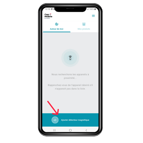
Sélectionner le détecteur magnétique parmi les produits proposés
Etape 2
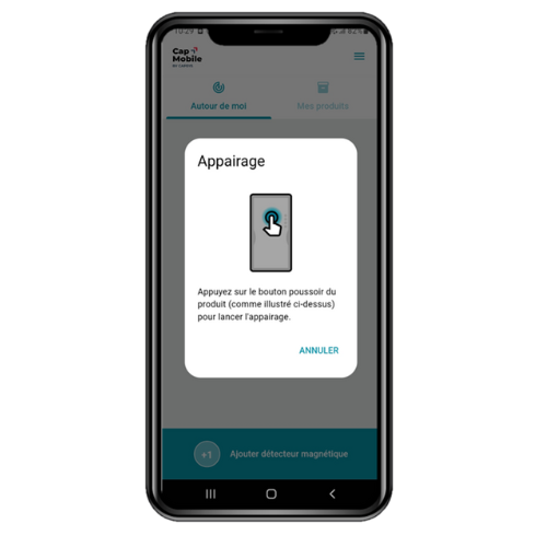
Appairer le détecteur avec l‘application Cap’Mobile : appuyer sur le bouton d’appairage en face avant (action lors de la première connexion). La led bleue du détecteur clignote en face avant pour confirmer l’appairage
Etape 3
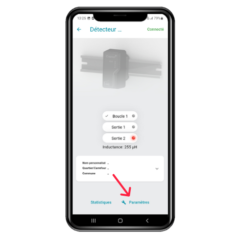
Puis cliquer sur Paramètres pour configurer le détecteur et ses sorties
Toutes les modifications de paramètres sont faites en temps réel.
QUICK START
Cabling
Install the detector in a metal enclosure that is grounded and complies with the Low Voltage Directive.
Step 1
Connect the socket with the power off and the detector unplugged (see table).
The outputs can be configured (NO or NC) once the detector is powered on, using the Cap’Mobile application.
Configuration
(Factory settings in bold)
| NUMBERED MARKS (SOCKET) | SINGLE CHANNEL | DUAL CHANNEL | ||
| STANDARD | SPECIAL VERSIONS | |||
| PLUG 5 POWER IN 1&2 | PLUG 6 COMPATIBLE PD13X | STANDARD DUAL | ||
| 1 | NO/NC OB | Power | Power | Power |
| 2 | Power | Power | Power | Power |
| 3 | NO/NC OB | NO/NC OB | NO/NC OB | Loop 1 |
| 4 | Ground | Commun OB | Ground | Loop 1 |
| 5 | NO/NC AO | NO/NC AO | NO/NC AO | Loop 2 |
| 6 | Commun AO | Commun AO | Commun AO | Loop 2 |
| 7 | Loop | Loop | Loop | NO/NC OB |
| 8 | Loop | Loop | Loop | Commun OB |
| 9 | Power | Ground | Reserved | Ground |
| 10 | Commun OB | NO/NC AO | Commun OB | COM AO |
| 11 | NO/NC AO | NO/NC OB | NO/NC AO | NO/NC AO |
| Device power on, off detection Non-polarized power / OA=output A / OB = output B | ||||
Status of the output contacts for presence and technical fault
(Factory settings in bold)
| PRESENCE | HORS TENSION | SOUS TENSION | ||
| HORS DETECTION | DETECTION | DEFAUT | ||
| NO | Closed | Open | Closed | Closed |
| NC | Closed | Closed | Open | Open |
| Led | Off | Off | On | Blinking |
| TECHN. DEFECT | POWER OFF | POWER ON | |
| NO DEFECT | DEFECT | ||
| NC | Open | Closed | Open |
| NO | Open | Open | Closed |
| Led | Off | On | Off |
Warning : once the detector is powered, the output LED configured as a technical fault is on unless technical fault
Step 2
Plug the detector into its base.
Configuration and testing
With the Cap’Mobile application, optimize the use of MAG-FLEX detectors
- Parameter modification
- Configuration of outputs: NO/NC,…
- Access to inductance and frequency information
- Real-time visualization of detections
- Access to product information (serial number,…) and event log
Download the Cap’Mobile app on your smartphone and create a user account.
Android (minimum V4.4)
Download : Cap’Mobile Android
IOS ( minimum V11)
Download : Cap’Mobile IOS
Once logged into Cap’Mobile :
Step 1
Select the magnetic detector from the list of available products
Step 2
Pair the detector with the Cap’Mobile app: press the pairing button on the front (this action is required during the first connection). The blue LED on the front of the detector will flash to confirm the pairing
Step 3
Then click on ‘Settings’ to configure the detector and its outputs
All parameter changes are made in real-time.